|
Adding and Working With Diagram Objects |


|
|
Adding and Working With Diagram Objects |
|
Now that you have specified both the type of Data Diagram that you will be creating and selected some or all of your input data sources, you can proceed with adding objects to your Data Diagram. Below are a few examples of Adding Objects to your Data Diagram.
| • | Adding an additional data source like another XML file. |
| • | Adding a Join function to synchronize two data sources. |
| • | Adding a SQL query. |
| • | Adding a Function such as Sum, Count, or Logical Tests. |
In any of such cases, you will find specific directions on the usage and reasoning for these objects in the Design Guide section of the help documentation. This section is simply to demonstrate a usage example of how to add objects into your Data Diagram and how to work with them in the Design Surface.
Usage
After selecting Finish in the Data Diagram setup wizard, the BI Data Analyst will display the Design Surface for you to begin working. As shown in Figure 1, their will be a few objects currently displayed in the Design Surface dependent upon the objects you selected in the diagram setup. You will see your desired output object as well as the input objects selected in the setup wizard. You should note that a helpful Getting Started annotation is added in the Design Surface. You can delete this object by simply selecting and pressing Delete on your keyboard. Alternatively, you can right click on this object, and in the Application Bar at the bottom of the screen select Delete.
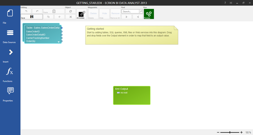
Figure 1: The first look at the Design Surface shows input objects, desired output object, and a helpful annotation.
Moving Objects in the Design Surface
In order to move an object in the Design Surface, use your mouse to navigate over the object you would like to move. You will need to move the mouse over the desired object until a four way directional arrow indicates when you should press the left mouse button and hold. With the left mouse button still depressed, move the mouse to move the object accordingly in the Design Surface. You will notice a shape outline is present in the Design Surface when you are dragging any object. This simple functionality is very important for you to provide visual organization to your Data Diagrams.
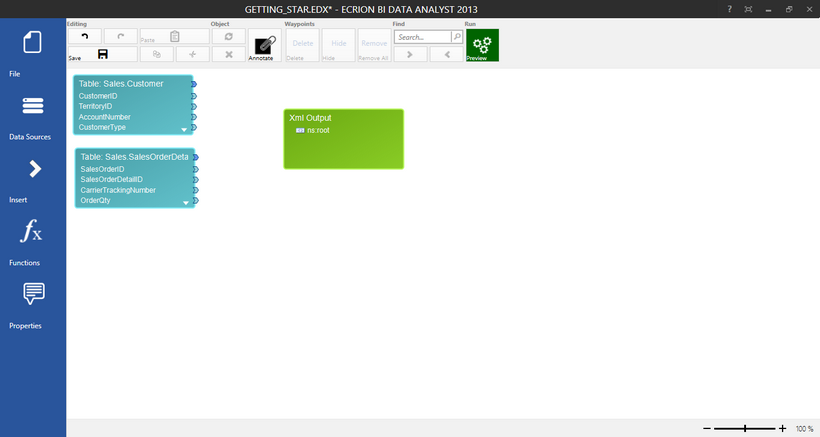
Figure 2: Objects are moved in the Design Surface by selecting and dragging.
Resizing Objects in the Design Surface
As you can view in Figure 2, both of our Input Objects do not display all of the available data points. While you can use the arrows located at the right of the Object to navigate the data within, you can also resize your Data Diagram Objects to expand the view of the information within. To resize any object, simply use your mouse to select the Object. Once the Object is selected, you will notice four boxes located at the corners of the selected object. You can select any one of these corner markers to drag and resize accordingly.
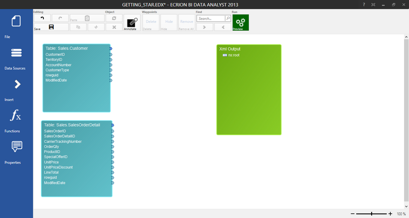
Figure 3: All Objects are resized in the Design Surface to show more information in the Data Diagram.
Inserting Other Objects
You may be aware that you have other requirements for your needed Output Data Object. Examples of some of these operations may include:
| • | Filtering your data source for inclusion in your output data object. |
| • | Performing operations like summing and counting. |
| • | Performing logical test on your data. |
| • | Concatenating two present values to make one field in your desired output. |
In the Side Menu, you will have access to both Functions and Insert dialogs. You will need to use these two menu options to insert objects that will meet your requirement. For example, if you were in need of adding another Database Table, you would need to use the Insert Dialog. If you are in need of concatenating two fields in a table, you would need to use the Functions dialog to select that function.
The first step is to determine what object you will need to work with to accomplish your goal. We will take the requirement below to demonstrate using the Side Menu to add and work with an object in the Design Surface.
Scenario: As seen in Figure 3, we will need to combine the SalesOrderID field with a '-' character and the ProductID to produce a new field in our output that will show a value such as "xxxxx-xxx" (SalesOrderID - ProductID).
The first step is to understand which function to use. We will need to select the Concatenate function available in the Functions dialog. To do so, simply select Functions in the Side Menu. We can find this function in the String Functions category in the dialog. We will simply select the Concatenate Function and notice that in the Design Surface the correct Concat function objects will be inserted. As you can see in Figure 4, by default the Concatenate Function has two Parameters.
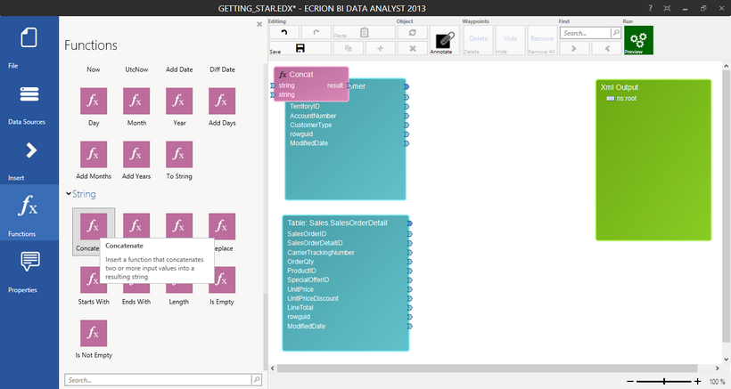
Figure 4: The Concatenate Function is inserted into the Design Surface.
Our particular example requires 3 Parameters. Two string values and a Constant. Constants are used to represent values that will not be dynamic. In this example, we need to add a constant to represent the '-' character. Again, we will turn the Functions Dialog to accomplish this goal. In the Math Functions category, we can find the opportunity to insert a Constant. We will simply select the Constant option and notice that a Constant Object will be added into the Design Surface. We will then move these objects in between our input and out output objects.
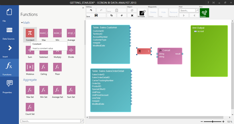
Figure 5: A Constant is added to be used with a Concatenate Function.
Modifying Objects
As you can tell, our example is not complete just yet. We will need to modify our inserted Objects to meet our needs. We will need to complete the following two tasks:
| • | Change the Constant type to be a string value for the '-'. |
| • | Change the Concatenate Function to accept another parameter. |
You can make such modifications by selecting the Object to edit and choosing Properties from the Side Menu. Or, you can simply double click on the Diagram Object to access the Properties Dialog.
To begin, we will double click on the Constant Object we have inserted and change the Value Type to String, and change the Value by adding the '-' character.
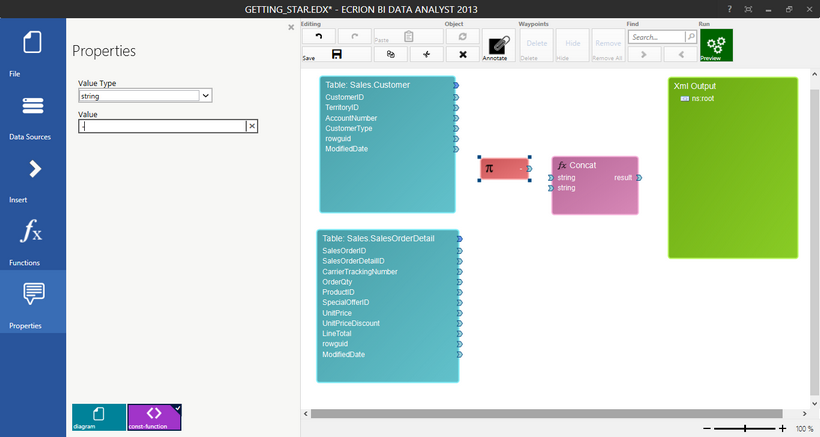
Figure 6: The Constant is modified to be a String Value Type with a '-' value.
Our next step is to add a Parameter to our Concatenate Function as, by default, the function only has two Parameters. To do so, we will Right Click on the Concatenate Function to access the Application Bar. In the Application Bar, you will notice an option to Add Parameter. We will simply select this option and notice that a Parameter is added in the Function.
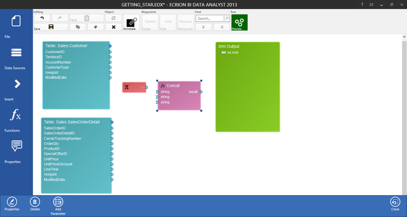
Figure 7: A Parameter is added by right clicking to access the Application Bar.
Now you know how to Insert, Resize, and Move Diagram Objects you will need to understand how to properly connect the Objects to obtain the output you desire. This section has been dedicated to helping you understand setting up these objects in the Design Surface. However, you will need to review our help section on Using Data Connections to complete your design.